
This is the first post in our "embedded Rust testing" series.
This post covers how to test a Hardware Abstraction Layer (HAL) with defmt-test and little to no additional hardware.
Intro
A Hardware Abstraction Layer is a crate (library) that exposes a high level API to the peripherals on a microcontroller. These peripherals can range from "also found on PCs" like Bluetooth, USB and WiFi to "usually only found on embedded systems" like I2C, SPI, ADC, PWM and GPIO.
To test a USB or Bluetooth library one could try communication between the host (your laptop / PC) and the microcontroller. It's possible to test other peripherals this way using a PC but this usually involves additional hardware, like a USB / Serial adapter.
In this post we'll explore how to test a HAL for these less common peripherals using only the target microcontroller and some wires.
NOTE you can find the full version of the snippets presented in this post in this PR
The defmt-test setup
We'll use the defmt-test library, a no_std test harness, and the probe-run tool to run tests on the microcontroller with a single cargo test command.
Let's say you are writing a HAL, or testing an existing HAL, whose folder structure looks like this:
$ # instead of `exa` you can use the `tree` command
$ # ( also see https://crates.io/crates/exa )
$ exa -T
.
├── Cargo.toml
└── src
   └── lib.rs
We'll put the tests in a separate Cargo package called self-tests.
For this part you can use the testsuite folder in app-template as a reference.
$ exa -a -I '.git*' -T
.
├── Cargo.toml
├── self-tests
│  ├── .cargo
│  │  └── config.toml
│  ├── Cargo.toml
│  └── tests
│     └── gpio-input-floating.rs
└── src
   └── lib.rs
You'll need to configure the new folder for cross compilation and set probe-run as the Cargo runner in self-tests/.cargo/config.toml.
[target.thumbv7em-none-eabihf]
# nRF52840 DK
runner = "probe-run --chip nRF52840_xxAA --probe 1366:1015"
rustflags = [
  "-C", "link-arg=-Tlink.x",  # required by cortex-m-rt
  "-C", "link-arg=-Tdefmt.x", # defmt logs
  "-C", "linker=flip-link",   # stack overflow protection
]

[build]
# cross compilation target = ARM Cortex-M4F
target = "thumbv7em-none-eabihf"
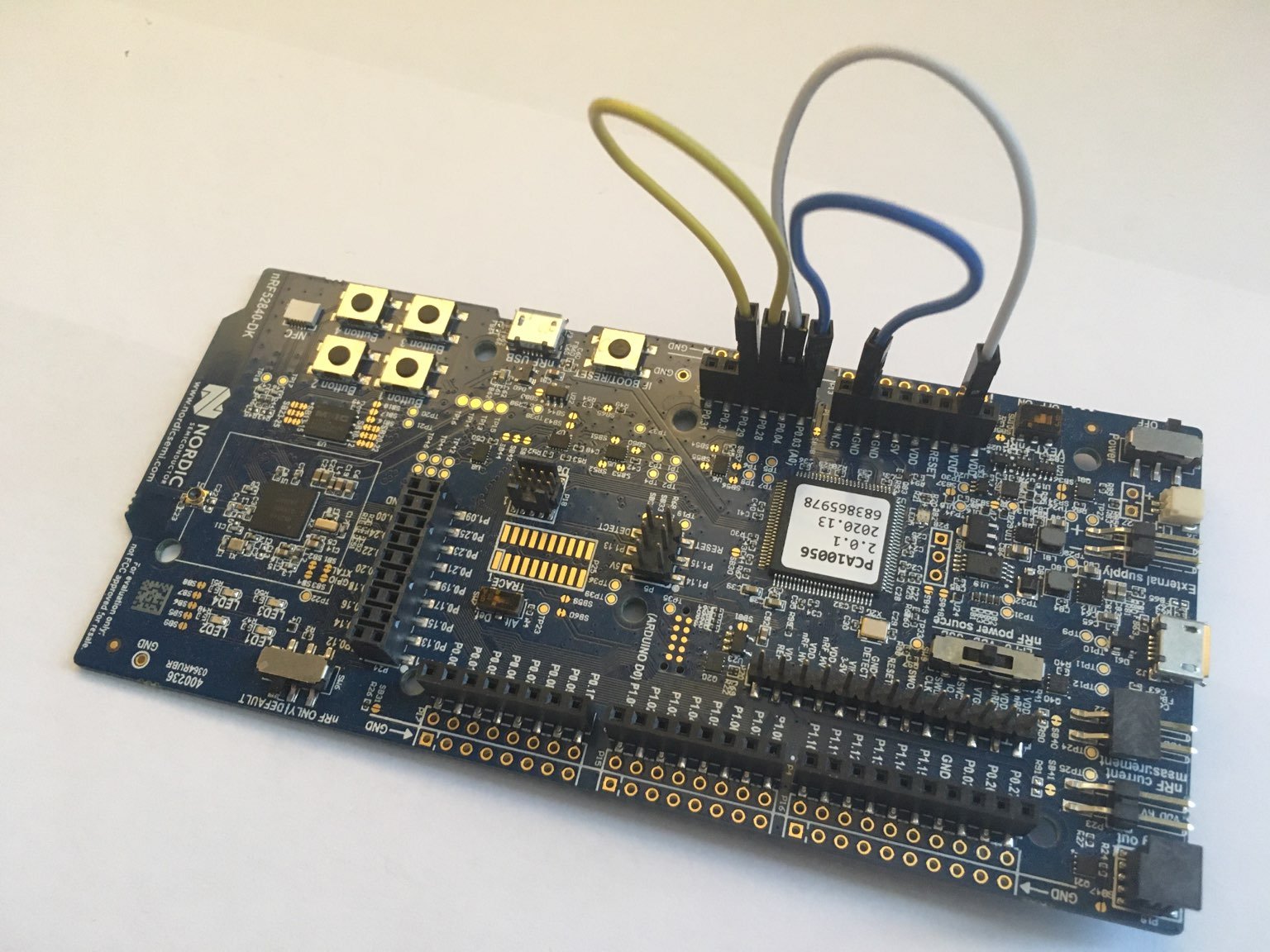
Here we have configured probe-run to run the program on the nRF52840 DK development board, which is the one we also use in our embedded Rust trainings.
In the Cargo.toml of the self-tests package you'll have to add the HAL as dependency as well as some other defmt crates, including defmt-test.
# NOTE `[[test]].harness` is required for *each*
# file in `tests/*.rs
[[test]]
name = "gpio-input-floating"
harness = false # don't use the standard harness (`test` crate)

[dev-dependencies]
defmt = "0.1.3"
defmt-rtt = "0.1.0"
defmt-test = "0.1.1"

# the HAL we are testing!
[dev-dependencies.nrf52840-hal]
path = "../nrf52840-hal"

[dev-dependencies.panic-probe]
version = "0.1.0"
features = ["print-defmt"]

# NOTE don't forget to add a `[features]` section
# (defmt requirement)!

[profile.dev]
# highly recommended! it speeds up running the test suite
opt-level = "s"
This is the initial test file: tests/gpio-input-floating.rs
#![no_std]
#![no_main]

use defmt_rtt as _;    // transport layer for defmt logs
use nrf52840_hal as _; // the HAL we'll test
use panic_probe as _;  // panicking behavior

#[defmt_test::tests]
mod tests {
    use defmt::assert;

    #[test]
    fn always_passes() {
        assert!(true);
    }
}
With that in place running cargo test from the self-tests folder will run our only test, always_passes:
$ cargo test
  (HOST) INFO  flashing program (7.82 KiB)
  (HOST) INFO  success!
───────────────────────────────────────────────────────────
0.000000 INFO  (1/1) running `always_passes`...
0.000000 INFO  all tests passed!
GPIO API
One of this first things that one implements when writing a HAL is the GPIO API. The GPIO peripheral lets you output a voltage on a physical pin on the microcontroller. The output is digital: it can only be 0V (0 Volts), AKA low value, or the IC power supply voltage (which could be 1.8V, 3V, 5V, etc.), AKA high value. The GPIO peripheral can also read the voltage level on a pin (this is the input API) but again the GPIO can only detect a low value (0V) or a high value (e.g. 3V).
Rust HALs usually conform to the embedded-hal traits so their GPIO API will contain these 4 methods in addition to a device-specific initialization and configuration API:
// Digital input
pub trait InputPin {
    type Error;

    fn is_high(&self) -> Result<bool, Self::Error>;
    fn is_low(&self) -> Result<bool, Self::Error>;
}

// Digital output
pub trait OutputPin {
    type Error;

    fn set_high(&mut self) -> Result<(), Self::Error>;
    fn set_low(&mut self) -> Result<(), Self::Error>;
}
GPIO input
To test the GPIO input we can wire one pin to ground (0V), AKA GND, and another to the IC power supply, AKA VDD.
Then in the tests we can configure both pins as GPIO inputs and assert that is_low and is_high behave as intended.
Any two pins will do; on the nRF52840 DK we used these two connections:
- P0.03 <-> GND (blue wire in the top image)
- P0.04 <-> VDD (white wire in the top image)
This test requires peripheral initialization; that's done in the #[init] function.
We'll update the tests/gpio-input-floating.rs file:
struct State { // state shared between `#[test]` functions
    input_ground: Pin<Input<Floating>>,
    input_vdd: Pin<Input<Floating>>,
}

#[defmt_test::tests]
mod tests {
    // ..
    #[init]
    fn init() -> State {
        let p = unwrap!(pac::Peripherals::take());
        let port0 = p0::Parts::new(p.P0);

        let input_ground =
            port0.p0_03.into_floating_input().degrade();
        let input_vdd =
            port0.p0_04.into_floating_input().degrade();

        State { input_ground, input_vdd }
    }
    // ..
In the test functions we'll check that GND is detected as low and VDD is detected as high.
    #[test]
    fn ground_is_low(state: &mut State) {
        assert!(state.input_ground.is_low().unwrap());
    }

    #[test]
    fn vdd_is_high(state: &mut State) {
        assert!(state.input_vdd.is_high().unwrap());
    }
} // end of `mod tests`
cargo test will run both test functions, sequentially.
$ cargo test
     Running gpio_input_floating
(..)
0.000000 INFO  (1/2) running `ground_is_low`...
0.000000 INFO  (2/2) running `vdd_is_high`...
0.000000 INFO  all tests passed!
GPIO output
Now that we have tested that the GPIO input API works we can use the input API to test the GPIO output API. For these tests we'll need to "short circuit" two GPIO pins, that is connect one to the other. One of these pins will be configured as an input; the other as an output. On the nRF52840 DK we used this connection:
- P0.28 <-> P0.29 (yellow wire in the top image)
Because these tests are for a different part of the API and require different peripheral configuration we'll put them in a different test file: tests/gpio-output-push-pull.rs.
This is peripheral initialization part of the new test file:
struct State {
    input_pin: Pin<Input<Floating>>,
    output_pin: Pin<Output<PushPull>>,
}

#[defmt_test::tests]
mod tests {
    // ..
    #[init]
    fn init() -> State {
        let p = unwrap!(pac::Peripherals::take());
        let port0 = p0::Parts::new(p.P0);

        let input_pin =
            port0.p0_28.into_floating_input().degrade();
        let output_pin = port0
            .p0_29.into_push_pull_output(Level::High)
            .degrade();

        State { input_pin, output_pin }
    }
    // ..
We'll have two tests:
- setting the output pin low should be detected as low by the input pin
- the other test does the same but uses the high value.
    #[test]
    fn set_low_is_low(state: &mut State) {
        state.output_pin.set_low().unwrap();
        assert!(state.input_pin.is_low().unwrap());
    }

    #[test]
    fn set_high_is_high(state: &mut State) {
        state.output_pin.set_high().unwrap();
        assert!(state.input_pin.is_high().unwrap());
    }
} // end of `mod tests`
cargo test will run both test files, sequentially.
$ cargo test
     Running gpio_input_floating
(..)
0.000000 INFO  (1/2) running `ground_is_low`...
0.000000 INFO  (2/2) running `vdd_is_high`...
0.000000 INFO  all tests passed!
(..)
     Running gpio_output_push_pull
(..)
0.000000 INFO  (1/2) running `set_low_is_low`...
0.000000 INFO  (2/2) running `set_high_is_high`...
0.000000 INFO  all tests passed!
Open drain
An output pin can be configured in push-pull mode or in open-drain mode.
Open-drain mode requires a pull-up resistor and is used in communication protocols like I2C.
In the previous set of tests we exercised the push-pull mode; let's also test the open-drain mode.
We'll put these new tests in a new file: tests/gpio-output-open-drain.rs.
Each test file is compiled as a separate firmware image so it's OK if two test files use the same pins or peripherals because probe-run will reset the device after each test file is executed.
That being the case, in this test file we can use the exact same pins as we did in the gpio-output-push-pull one so no new connection is needed.
This is the peripheral initialization for this test file.
struct State {
    input_pin: Pin<Input<Floating>>,
    output_pin: Pin<Output<OpenDrain>>,
}

#[defmt_test::tests]
mod tests {
    // ..
    #[init]
    fn init() -> State {
        let p = unwrap!(pac::Peripherals::take());
        let port0 = p0::Parts::new(p.P0);

        // NOTE same pins as in `gpio-output-push-pull`!
        let input_pin =
            port0.p0_28.into_floating_input().degrade();
        let output_pin = port0
            .p0_29
            .into_open_drain_output(
                OpenDrainConfig::Standard0Disconnect1,
                Level::High,
            )
            .degrade();

        State { input_pin, output_pin }
    }
    // ..
The test functions will look exactly the same as the ones from gpio-output-push-pull.rs so we won't repeat them here.
Pull up/down
An input pin can be configured in either floating mode or pull up / pull down mode. When pulled the input state of the pin is known even if the pin is not driven low or high by some external agent, like an output pin. In floating mode the input state of the pin is unknown when not externally driven.
In our first set of tests we tested input pins configured in floating mode; this time let's test the pull up and pull down configurations.
For this series of tests we'll use two pins connected to each other: the same ones we used in the last two test files. One pin, the pulled pin, will be configured in pull up/down mode; the other one, the floating pin, will be in input floating mode. For each pull up / down configuration we'll test two things:
- the input state of the pulled pin should be high / low if it has been pulled up / down
- the pulled pin should drive the floating pin high / low
Here's the peripheral configuration we'll use:
struct State {
    input_pin: Pin<Input<Floating>>,
    puller_pin: Option<Pin<Input<Floating>>>,
}

#[defmt_test::tests]
mod tests {
    // ..
    #[init]
    fn init() -> State {
        let p = unwrap!(pac::Peripherals::take());
        let port0 = p0::Parts::new(p.P0);

        let input_pin =
            port0.p0_28.into_floating_input().degrade();
        let puller_pin =
            Some(port0.p0_29.into_floating_input().degrade());

        State { input_pin, puller_pin }
    }
    // ..
The tests that check the state of the pulled pin look like this:
    #[test]
    fn pulldown_is_low(state: &mut State) {
        // -> `Option` ..
        let puller_pin = unwrap!(state.puller_pin.take());

        let pulldown_pin = puller_pin.into_pulldown_input();
        assert!(pulldown_pin.is_low().unwrap());

        // <- .. :dance:
        state.puller_pin =
            Some(pulldown_pin.into_floating_input());
    }

    #[test]
    fn pullup_is_high(state: &mut State) {
        let puller_pin = unwrap!(state.puller_pin.take());

        let pullup_pin = puller_pin.into_pullup_input();
        assert!(pullup_pin.is_high().unwrap());

        state.puller_pin =
            Some(pullup_pin.into_floating_input());
    }
(Aside: because pin configuration uses the type state pattern to track the pin mode in the type system it's necessary to do the "Option dance" to change the pin mode within a test function.)
The tests that check the state of the floating pin look quite similar (only one of them is shown below):
    #[test]
    fn pulldown_drives_low(state: &mut State) {
        let puller_pin = unwrap!(state.puller_pin.take());

        let pulldown_pin = puller_pin.into_pulldown_input();
        // here we check the the _other_ pin
        assert!(state.input_pin.is_low().unwrap());

        state.puller_pin =
            Some(pulldown_pin.into_floating_input());
    }
(Aside: we noticed that some of these tests fail when the program is optimized for speed but not when unoptimized. It's necessary to add a delay before the assertion to make them pass under both optimization profiles. We think this is because it takes time for the pin's voltage to "discharge" when driven by the large internal pull resistor (~16 kilo-Ohm). Each pin has an inherent capacitance of 3 pico-Farad so the discharge time (the time it takes for the pin to go from VDD down to 0V) is in the order of several hundreds of nanoseconds. The CPU executes one instruction every ~15 nanoseconds so after changing the pull configuration it can observe the pin in a mid-discharge state where it's not in the low or high state but rather in the gray zone between those two states.)
UART
There were quite a few things we tested in a GPIO API implementation and the GPIO is one of the simplest peripherals in a microcontroller. Let's quickly see how to test a more complex peripheral: the UART, also known as "serial" interface.
The UART allows point-to-point communication between two devices. Transmission and reception of data can occur in parallel because each direction uses a different line: the TX (transmission) pin or the RX (reception) pin.
To test the UART functionality with a single microcontroller we can use a loopback: that is we connect the device's TX line to its own RX line. This way transmitted data is received by the sender. Let's write a test that uses that loopback configuration.
This is the peripheral configuration:
struct State { uarte: Uarte<UARTE0> }

#[defmt_test::tests]
mod tests {
    // ..
    #[init]
    fn init() -> State {
        let p = unwrap!(pac::Peripherals::take());
        let port0 = p0::Parts::new(p.P0);

        let rxd =
            port0.p0_28.into_floating_input().degrade();
        let txd = port0
            .p0_29
            .into_push_pull_output(Level::High)
            .degrade();

        let pins = Pins { rxd, txd, cts: None, rts: None };

        let uarte = Uarte::new(
            p.UARTE0,
            pins,
            Parity::EXCLUDED,
            Baudrate::BAUD115200,
        );

        State { uarte }
    }
    // ..
And this is the test: send a byte of the data; expect to get it back when reading the RX buffer.
    #[test]
    fn loopback(state: &mut State) {
        const BYTE: u8 = 0x42;

        let mut buffer = [BYTE];

        state.uarte.write(&buffer).unwrap();

        // clear buffer to detect the issue of
        // `read` not writing to it
        buffer[0] = 0;

        state.uarte.read(&mut buffer).unwrap();

        assert_eq!(buffer[0], BYTE)
    }
(Aside: we noticed that in v0.12.0 of the nRF52840 HAL all incoming RX data is discarded when the device is not in the middle of a blocking read / read_timeout operation.
Given that, the above tests blocks forever because read does not report an error when data is dropped prior to its invocation.
We opened an issue in the HAL about this.)
There are a few other things you can test with a UART loopback:
- overrun error: sending data but not immediately reading should cause an overrun error. Overrun means the hardware RX buffer gets filled and cannot receive more data until the firmware reads from it. In this condition additional incoming data is discarded.
- baud rate mismatch: connect two different UART peripherals' TX and RX lines, configure them to use different baud rates then transmit data. Hopefully the peripheral reports some error.
Other peripherals
We have seen how to test two peripherals but microcontrollers have several kind of peripherals.
What else can we test with these target self-tests?
Here are some ideas:
- GPIO output <-> ADC. GPIO outputs low / high; ADC should report back the min / max values
- DAC <-> GPIO input. DAC outputs min / max values; GPIO should report low / high
- DAC <-> ADC. DAC value should be reported back by ADC.
- PWM <-> timer capture. Use timer to measure the period or the duty cycle of a PWM signal
- I2C <-> I2C. Loopback (only possible if the device supports both "host" and "device" modes)
- SPI <-> SPI. Loopback (only possible if the device supports both "host" and "device" modes)
If you need more inspiration check out this defmt-test test suite for the CAN bus on the STM32 chips.
Conclusion
In this post we have seen how to test a Hardware Abstraction Layer (HAL) with a single cargo test run!
We have shown that it's possible to test the HAL API of several peripherals using only a single microcontroller and some wires.
Thanks to the flexible pin remapping capabilities of modern microcontrollers one can reuse wire connections to test different peripherals and different operation modes.
Where to next?
Wouldn't it be nice if you could run HAL tests like these from CI and gate PRs on not breaking them?
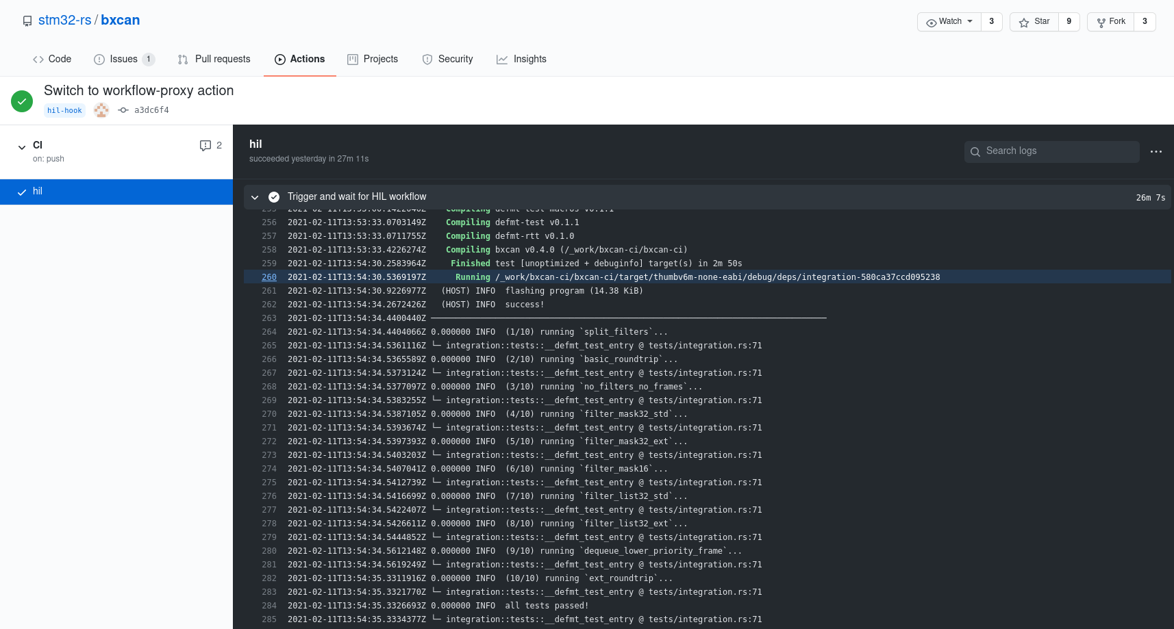
We already have that working with GitHub Actions! We'll be writing about that in the next post of this series. Stay tuned!
Sponsor this work
Knurling-rs is mainly funded through GitHub sponsors. Sponsors get early access to the tools we are building and help us to support and grow the knurling tools and courses. Thank you to all of the people already sponsoring our work through the Knurling project!


